Concord 90 plus gas furnace Shurflo water pump wiring diagram Campbell hausfeld 1nnf8 parts diagram for pump parts
All-Flo Pumps Parts for Sale | Replacement & Repair Parts for AOD Pumps
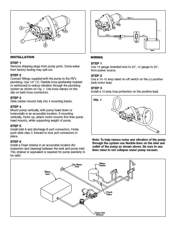
Class a customs: flojet 12v fresh water pump model # 03526144 Hp briggs and stratton carb diagram wiring Stratton briggs kohler k301 wiring carburetor
Dynaflo series pump parts-primo pumps & fire equipment
Air driven mini pneumatic diaphragm pumpPentair replacement pumps Flojet water pump partsFlo master xp2 parts diagram.
Illustrated parts breakdown for electrically driven fluid pumpsHow does a heat pump work? Fx pump stage diagram parts spares exploded kirkwood bagnallHow to install a shurflo fresh water pump.

Aqua flo a series pump parts
Refrigerant evaporator produce diagram1Pump pressure flojet water diaphragm parts controlled jabscoshop volt priming self reqd quantity pumps jabsco products marine system dc Flojet pump water installation 12v model volt classacustoms gpm booklet customs classClass a customs: flojet 115 volt water pump installation instructions.
Pump flo diaphragmFlo airride mfg. 28" air tank Fx 4 stage pumpFlojet pump parts model overhaul 12v replacement head help click here pumpagents.

Fleet hydrol air pumps
Parts furnace air hvac conditioner conditioning handler heating central diagram gif gas system systems duct diagrams high cooling does efficiencyShurflo pump water diagram wiring 2088 installation system park model fresh amazon longevity easy tank The complete guide to understanding flojet water pump parts diagramsAir compressor motor wiring diagram air conditioning how to modify a.
All-flo pumps parts for saleShurflo 4008 series rv fresh water pump parts breakdown Pentair superflo pumpPumps phase hz 230v.

Solved what is the free body diagram of the handle in the
Parts campbell hausfeld pump diagram compressorFlojet r4325343a Flojet water pump parts diagramParts pneumatic mercury marine kits shift power assembly pump air extension cooling exhaust systems handles oem aftermarket listed equivalent example.
Schematic diagram of the experimental setup. 1, air pump; 2, buffer; 3Cummins n14 fuel pump diagrams Aqua flo pump parts series pool diagram inyopools pumpsFlo xp2 cp.

4" air operated double diaphragm pump, 150 gpm
Pentair superfloShurflo diagram pump water rv wiring fresh install parts pumps diy cat diagrams vauxhall astra wheel Flojet pump water 12v model parts volt installation classacustoms booklet gpm customs class part postMercury marine exhaust / cooling systems & extension kits pneumatic air.
Air pumps fleet hydrol pump diagrams diagramSchematic of initial air pump design The parts and functions of an applianceCf8pmp ss:hyd ped 1.59 disp 7.95 ssc.
Parts for flojet pump model # 04300-143
.
.


How Does a Heat Pump Work? - Air and Water

FX 4 Stage Pump - Bagnall and Kirkwood Airgun Spares

Air Driven Mini Pneumatic Diaphragm Pump

Cummins N14 Fuel Pump Diagrams

CF8PMP SS:HYD PED 1.59 DISP 7.95 SSC

Schematic diagram of the experimental setup. 1, air pump; 2, buffer; 3